
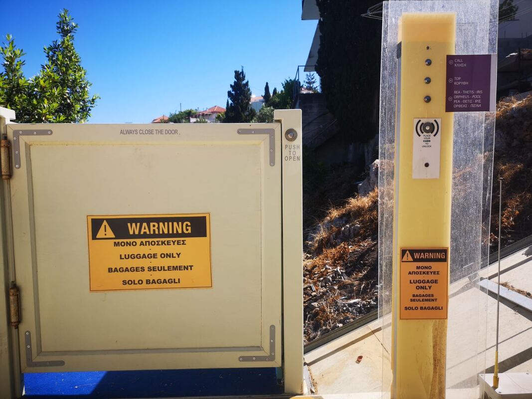
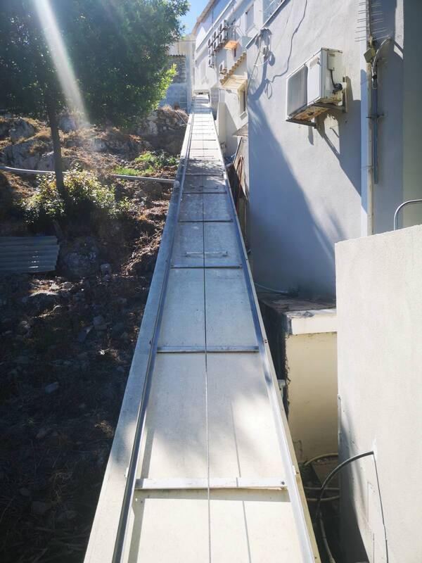
3 FLOOR ELEVATOR PROJECT
|
|
|
USING PLC LOGO! 8.3
After the big demand on the boards and due to the lack of time i decided to program a cheap industrial plc to do exact the same job as the arduino board. This is an all weather , all time non stop solution! Despite that i realized that none of my arduino stopped working after a lot of years too...
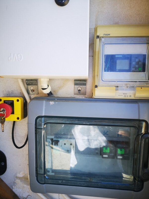
ELECTRICAL DIAGRAM OF THE ELEVATOR PARTS
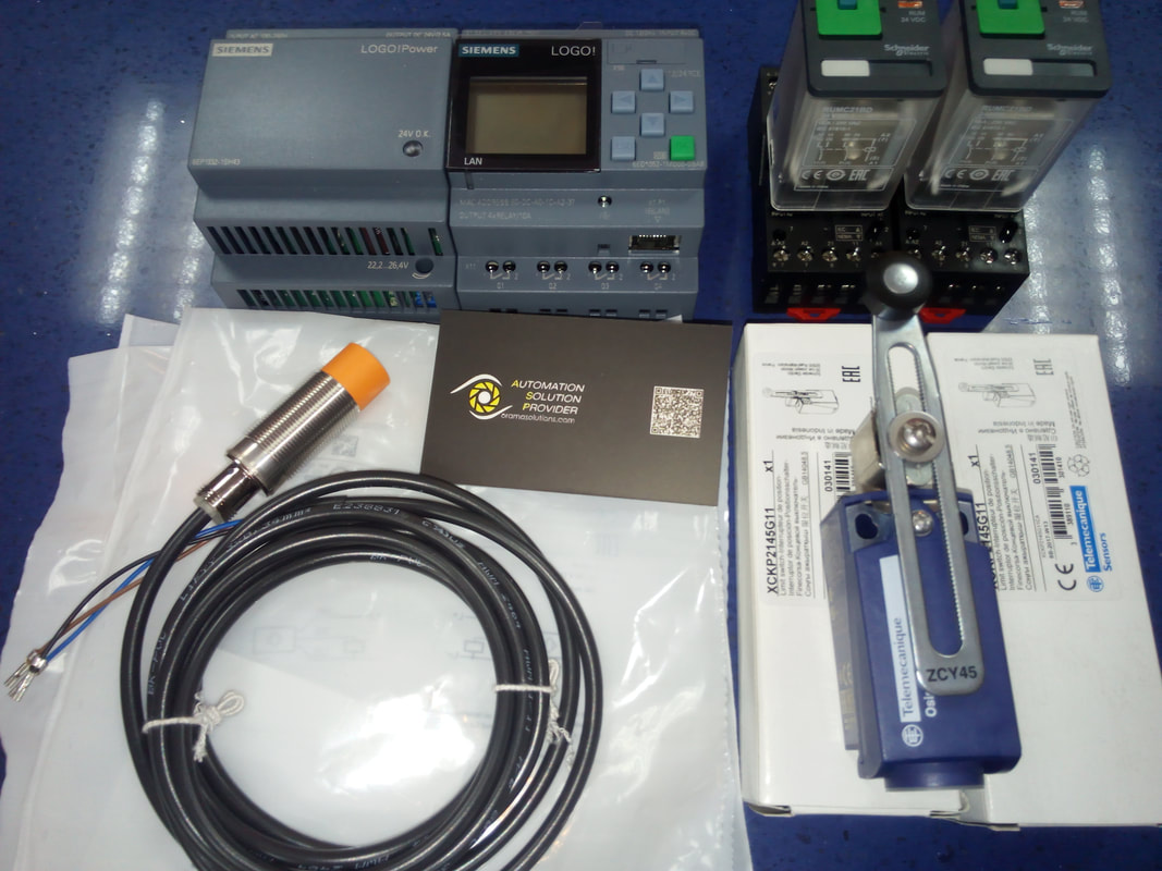
ELEVATOR PARTS
You will need:
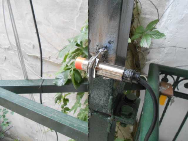
3 x inductive sensors
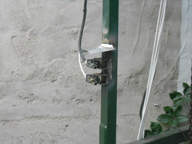
2 x terminal switches
1 x plc logo 8.3
1 x power supply 1.3A 24vdc
2 x High power relay
1 x Motor
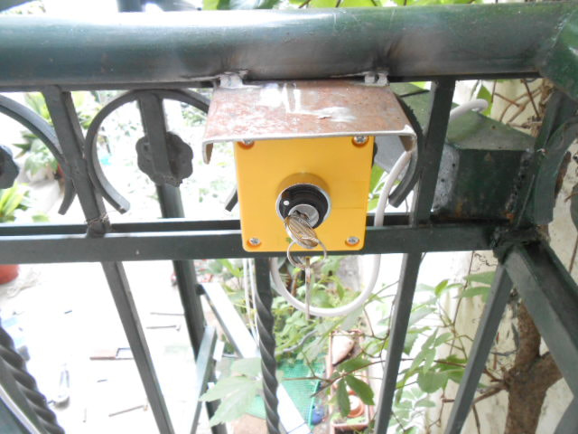
- buttons for commands
- alarm indicators
- safety switches
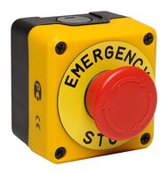
- emergency stop switches
3 x inductive sensors
2 x terminal switches
1 x plc logo 8.3
1 x power supply 1.3A 24vdc
2 x High power relay
1 x Motor
- buttons for commands
- alarm indicators
- safety switches
- emergency stop switches
|
|
|
|
|
|
PLC SELECTION
|
The LOGO! 24 CE - 6ED1052-1CC08-0BA1 logic module from Siemens with color-changeable display has an IP20 protection rating and works with a power supply of 24 VDC. Up to 400 function blocks can be processed. The device has 8 digital inputs, 4 of which can be used in analog mode (0-10 V), as well as 4 digital outputs (transistor). The LOGO! 24 CE - 6ED1052-1CC08-0BA1 micro PLC with display is programmable via Ethernet interface.
|
| ||
POWER SUPPLY SELECTION
|
The LOGO! POWER 24V 1,3A - 6EP3331-6SB00-0AY0 switched mode power supply unit from Siemens with an output voltage of 24VDC and an output current of 1.3A is the ideal power supply for the LOGO! mini controllers. The LOGO! POWER 24V 1,3A - 6EP3331-6SB00-0AY0 switched mode power supply unit provides high performance in minimum space. Enhanced efficiency across the entire load range and low power losses in no-load operation ensure efficiency.
|
| ||
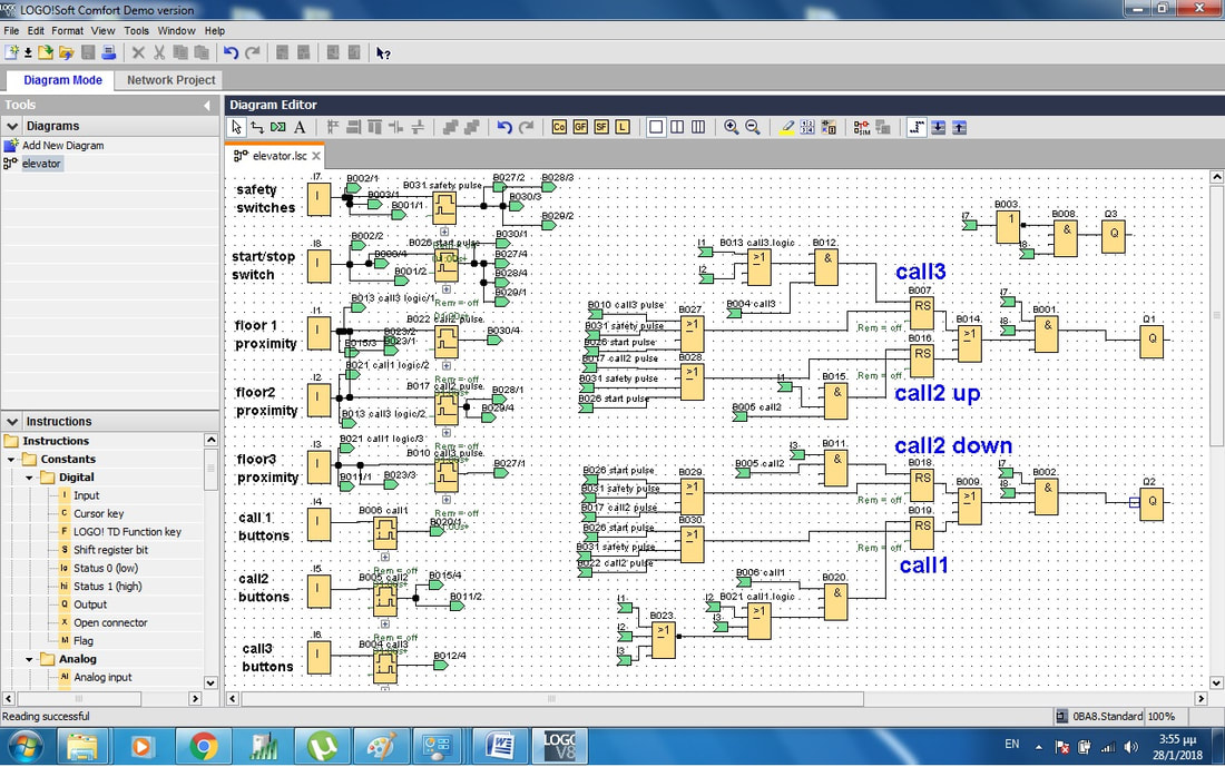
THE PROGRAM
As long as we use siemens logo plc 8.3 we use logo soft comfort 8.3 to program it with a network project.
INPUTS
I1 = Floor 1 ,signal from inductive sensor
I2 = Floor 2 , signal from inductive sensor
I3 = Floor 3 , signal from inductive sensor
I4 = Signal from/to floor 1 , cabinet button in parallel connection with the floor 1 button
I5 = Signal from/to floor 2 , cabinet button in parallel connection with the floor 2 button
I6 = Signal from/to floor 3 , cabinet button in parallel connection with the floor 3 button
I7 = Error check Input. Here you connect all the emergency stop switches and terminal switches of the doors in series.
Ι8 = Start Switch.
OUTPUTS
Q1 = Up direction of the motor, M connected to A1 relay up
Q2 = Down direction of the motor , M connected to A1 relay down
Q3 = Alarm output that indicates error regarding to input 7
Q4 = N.C.
Q2 = Down direction of the motor , M connected to A1 relay down
Q3 = Alarm output that indicates error regarding to input 7
Q4 = N.C.
OPERATION
- For the program to run I7 Input must be high. (terminal switches and emergency stop contacts.
- For the program to run I8 Input must be high. (main switch)
- If I8 is high and I7 isn’t high Q3 goes high to energize the alarm.
- Inputs Ι4, Ι5, Ι6 that corresponds to call buttons must be high for at least a second to be valid
- If Input I1 is high the elevator can go only in up direction. This means that I4 Is de-energized. If I5 or I6 goes high for at least a second then Q1 output goes high till elevator reach the corresponding floor.
- If Input I2 is high the elevator can go in both up and down directions. In this case I5 input is de-energized. If I4 or I6 goes high for at least a second then Q1 for up direction or Q2 for down direction goes high till elevator reach the corresponding floor.
- If Input I3 is high the elevator can go only in down direction. This means that I6 Is de-energized. If I4 or I5 goes high for at least a second then Q2 output goes high till elevator reach the corresponding floor.
- If none of the inputs Ι1, Ι2, Ι3 isn’t high then the elevator can go only down so the only input that is not de-energized is
- The movement of up or down direction will stop when the corresponding input of the floor goes high
- The movement of up or down direction will stop when the I7 input goes low. The program will reset.
- The movement of up or down direction will stop when the I8 input goes low. The program will reset.
|
|
