usb e kits presents
color organ V2
|
|
|
functionality
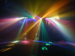
A very cool 2 channel Color Organ kit! Lay back and watch Leds dance on the music!
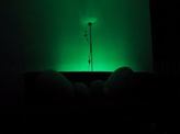
5 green leds for the low frequencies (bass) and 5 blue leds for the high frequencies (treble)
The kit is based on a quad amplifier (LM324).
Just drive an audio signal of an analog output (e.g. soundcard) direct to the audio jack of the kit.
Use an audio splitter if you have only one output.The cable can be both mono and stereo.
The audio signal now is ready to travel through the opamps.
The 2 first opamps of the LM324 are active filters that separate the low and high frequencies.
The other 2 opamps are amplifying the separated signals separately. With two potentiometers you can adjust the amplification to the level you want accordingly to the input audio signal strength.
Now the new signals trigger 2 npn transistors (2N3904) ,one for the low frequencies
and one for the high frequencies.The transistors drive the green and blue high brightness straw hat leds!
After your feedback from the first version we made some improvements
please leave your feedback for the kit or your suggestions for more improvements in the future
|

|
V2 release improvements
1) Reverse polarity protection
2) Redusing the noise in the nets with better pcb wirrings and adding capacitors above the chips.
3) Bigger pads for easier constructions
4) Better placing of the components for easier constructions
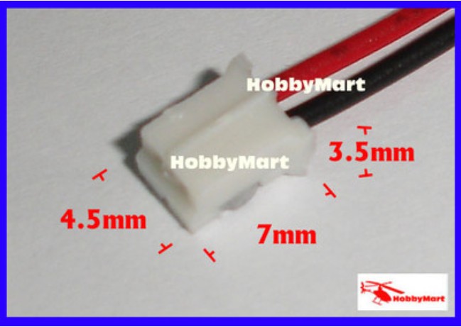
5) The on off switch now is extended from the pcb so you can mount it in your project box
6) More leds per channel for more intensity and better placing for better optical results.
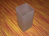
7) Ability to place the led on the bottom side so you can hide the rest of the structure.
8) The trimmers are now extended from the pcb board so you can mount them in your project box.
9) Bigger heat sink power plates for better heat consumption.
10) A bigger amplification of the audio signal.
11)Better seperation of 2 channels.
2) Redusing the noise in the nets with better pcb wirrings and adding capacitors above the chips.
3) Bigger pads for easier constructions
4) Better placing of the components for easier constructions
5) The on off switch now is extended from the pcb so you can mount it in your project box
6) More leds per channel for more intensity and better placing for better optical results.
7) Ability to place the led on the bottom side so you can hide the rest of the structure.
8) The trimmers are now extended from the pcb board so you can mount them in your project box.
9) Bigger heat sink power plates for better heat consumption.
10) A bigger amplification of the audio signal.
11)Better seperation of 2 channels.
Update v2.2
I've changed the values of the resistors R11 , R12 , R6.
This is for the amplification level of the signal.
I think that the previous values offered bigger amplification than we wanted.
So now we have more flexibility with the audio levels of the signal.
Also i added an extra resistor to the circuit exactly on the audio input connected from the signal direct to the ground.
This now the green leds will not turn on when the audio jack cable isn't connected...
New values: R6 =10K , R11=4,7K , R12=10K , R14 = 1.2M
the circuit schematic
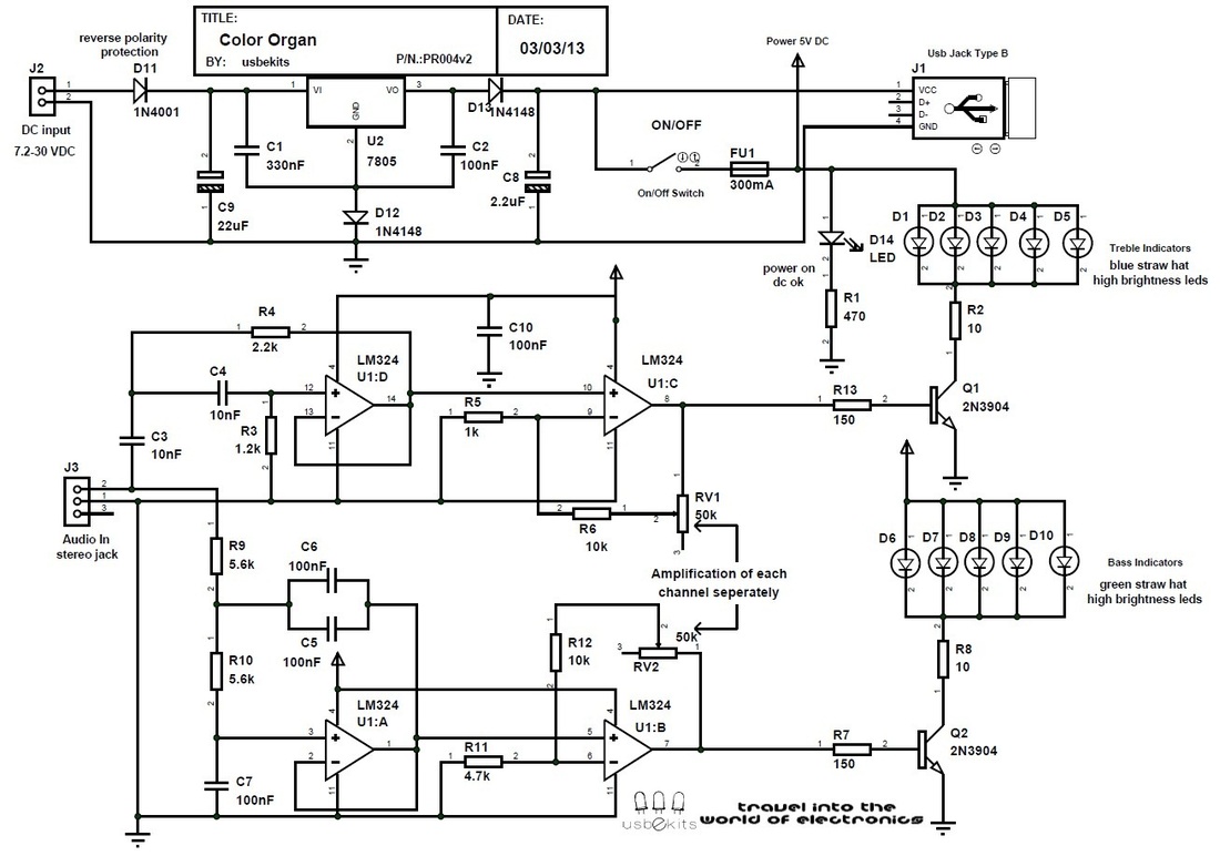
color organ schematic
part list
Ref. Type Value
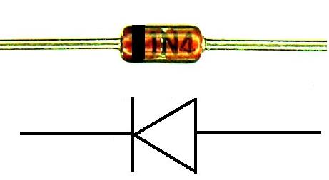
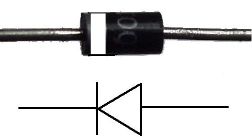
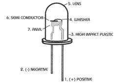
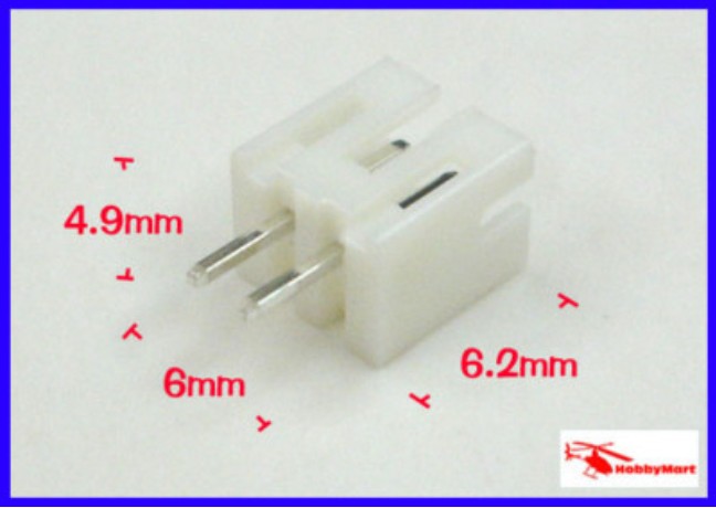
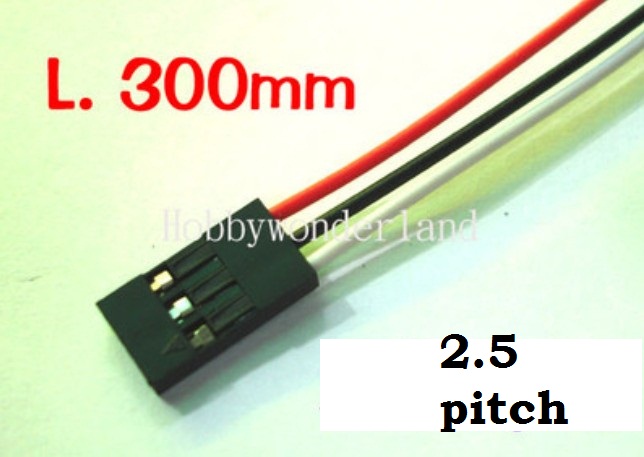
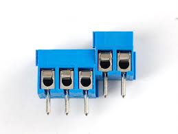
C1 Ceramic Capacitor 330nF C2 Ceramic Capacitor 100nF C3 Ceramic Capacitor 10nF C4 Ceramic Capacitor 10nF C5 Ceramic Capacitor 100nF C6 Ceramic Capacitor 100nF C7 Ceramic Capacitor 100nF C8 Electrolytic Capacitor 2,2uF C9 Electrolytic Capacitor 22uF C10 Smd 0603 Capacitor 100nF D1 Straw hat LED Blue D2 Straw hat LED Blue D3 Straw hat LED Blue D4 Straw hat LED Blue D5 Straw hat LED Blue D6 Straw hat LED Green D7 Straw hat LED Green D8 Straw hat LED Green D9 Straw hat LED Green D10 Straw hat LED Green D11 Diode 1N4001 D12 Diode 1N4148 D13 Diode 1N4148 D14 3mm difused led Green FU1 Fuse glass 20mm 300ma J1 Usb jack Type B J2 Terminal Block 2 pin Dc input J3 Audio jack stereo Audio input SW1 jst 2 pin connector ON/OFF Switch U2 Voltage Regulator 7805 Q1 NPN Transistor 3904 Q2 NPN Transistor 3904 R1 Resistor 1/4 watt 470 R2 Resistor 1/4 watt 10 R3 Resistor 1/4 watt 1,2k R4 Resistor 1/4 watt 2,2k R5 Resistor 1/4 watt 1k R6 Resistor 1/4 watt 10k R7 Resistor 1/4 watt 150 R8 Resistor 1/4 watt 10 R9 Resistor 1/4 watt 5.6k R10 Resistor 1/4 watt 5.6k R11 Resistor 1/4 watt 4.7k R12 Resistor 1/4 watt 10k R13 Resistor 1/4 watt 150 R14 Resistor 1/4 watt 1,2M U1 Quad Opamp Lm324 RV1 jst 3pin cable Trimmer 50k RV2 jst 3pin cable Trimmer 50k |
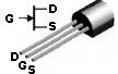
construction help guide
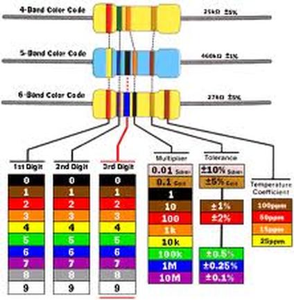
resistor color code definition
|


downloads
| color_organ_v2.2_datasheet.pdf |
| merged_color_organ__v2_pcb_files.pdf |
how to drive one channel of your soundcard output to the kit
Split your audio signal
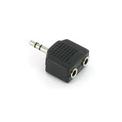
If your soundcard doesn't have more than one output you can split the audio signal with a simple audio splitter!
So you can here the music while seeing the leds dancing!
If you have more than one outputs you can take one free output directly.
So you can here the music while seeing the leds dancing!
If you have more than one outputs you can take one free output directly.
Use a male to male audio stereo jack cable.

Now simply drive the cable from spliter or soundcard
directly to the female audio jack of the color organ kit.
directly to the female audio jack of the color organ kit.
Troubleshooting
If you cant see the leds dancing one of the following may be the cause:
The audio signal is too week-->Increase the volume of the device
The audio signal is good --> Adjust the sensitivity of the trimmers
The audio signal is too week-->Increase the volume of the device
The audio signal is good --> Adjust the sensitivity of the trimmers
Choose the way you want to operate the kit!
|
|
|
|
|
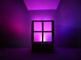
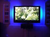
Watch your led dance on the music
or on the sounds of a film!