
prototype and soldering tips by usb e kits
first of all lets consinder a few basics in building electronic circuits in pcbs:
Necessary Tools
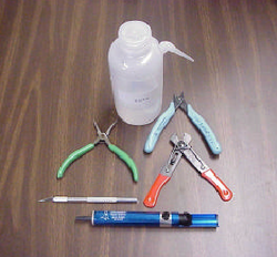
This is the recommended minimum complement of tools for soldering:
A. Miniature needle-nose pliers
B. Miniature side cutters
C. Wire strippers
D. Solder removal tool (“Solder Sucker”)
E. Water bottle
F. Safety glasses
the board
Is made of a thin insulating material clad with a thin layer of conductive copper that is shaped in such a way as to form the necessary conductors between the various components of the circuit. The use of a properly designed printed circuit board is very desirable as it speeds construction up considerably and reduces the possibility of making errors. To protect the board during storage from oxidation and assure it gets to you in perfect condition the copper is tinned during manufacturing and covered with a special varnish that protects it from getting oxidised and also makes soldering easier.
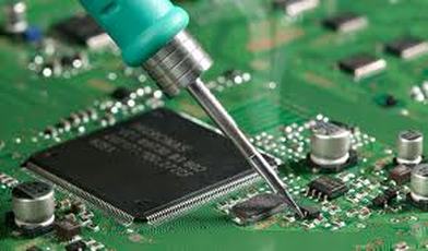
soldering the components
|
From the way you do it depends greatly your success or failure. This work is not very difficult and if you stick to a few rules you should have no problems. The soldering iron that you use must be light and its power should not exceed the 25 Watts. The tip should be fine and must be kept clean at all times. For this purpose come very handy specially made sponges that are kept wet and from time to time you can wipe the hot tip on them to remove all the residues that tend to accumulate on it.
|
|
warnings

|
DO NOT file or sandpaper a dirty or worn out tip. If the tip cannot be cleaned, replace it. There are many different types of solder in the market and you should choose a good quality one that contains the necessary flux in its core, to assure a perfect joint every time. DO NOT use soldering flux apart from that which is already included in your solder. Too much flux can cause many problems and is one of the main causes of circuit malfunction. If nevertheless you have to use extra flux, as it is the case when you have to tin copper wires, clean it very thoroughly after you finish your work. |
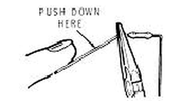
point-to-point construction help
|
Point-to-point techniques are used
when the expense of designing a PCB is prohibitive or as the prelude to the design of a PCB. Wiring typically uses either plain perforated board (“perf-board”) or “pad per hole” perf -board.
Pad per hole boards have a plated-through eyelet, or pad, at each hole. Are more expensive, but are highly recommended because the eyelets ensure that components are physically held to the board. In either case, wires must be wrapped around each other or around the pins of components to make connections. Soldering methods are approximately the same as for PCBs. there is an online tool that help you design a breadboard circuit before contruct it.
|
in this video get useful info about the assembly of a breadboard
|

Component mounting
Components are pushed through from the top side of the
board and the leads are bent slightly to hold the component while soldering. |
|
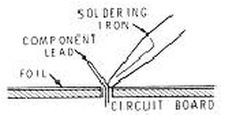
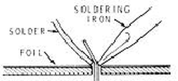
Soldering Techniques
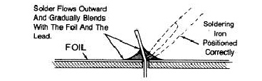
a. The soldering iron tip should be placed in contact with both the trace (foil)
and the lead. The two should be heated only enough to melt solder in order to avoid damaging sensitive components and to avoid delamination of the PCB traces. b. Solder is then touched to the area and allowed to flow freely around the lead and to cover the solder pad. A minimal amount of solder should be applied. Only enough solder to cover the joint and to form a smooth fillet should be used. c. The iron should be removed after the solder has flowed properly and wetted all surfaces. The component and the board should not be moved until the solder has hardened (up to several seconds, depending on the lead and trace size). |
|
Solder inspection
a. Qualities of good solder joints:
1. Shiny surface. 2. Good, smooth fillet. b. Qualities of good solder joints 1. Dull or crystallized surfaces. This is an indicator of a cold solder joint. 2. Floaters. Black spots “floating” in the solder 3. Balls. A solder ball, instead of a fillet. 4. Excess Solder. 5. Dimples. 6. Air pockets. |
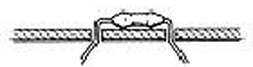
Good Solder joint.
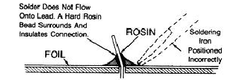
Poor solder joints
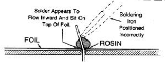
Poor solder joints
|
Help videos for good solders
notes
In order to solder a component correctly you should do the following:
- Clean the component leads with a small piece of emery paper.
- Bend them at the correct distance from the components body and insert he component in its place on the board.
- You may find sometimes a component with heavier gauge leads than usual, that are too thick to enter in the holes of the p.c. board. In this case use a mini drill to enlarge the holes slightly. Do not make the holes too large as this is going to make soldering difficult afterwards.
- Take the hot iron and place its tip on the component lead while holding the end of the solder wire at the point where the lead emerges from the board. The iron tip must touch the lead slightly above the p.c. board.
- When the solder starts to melt and flow wait till it covers evenly the area around the hole and the flux boils and gets out from underneath the solder.
- The whole operation should not take more than 5 seconds. Remove the iron and allow the solder to cool naturally without blowing on it or moving the component. If everything was done properly the surface of the joint must have a bright metallic finish and its edges should be smoothly ended on the component lead and the board track. If the solder looks dull, cracked, or has the shape of a blob then you have made a dry joint and you should remove the solder (with a pump, or a solder wick) and redo it. Take care not to overheat the tracks as it is very easy to lift them from the board and break them.
- When you are soldering a sensitive component it is good practice to hold the lead from the component side of the board with a pair of long-nose pliers to divert any heat that could possibly damage the component.
- Make sure that you do not use more solder than it is necessary as you are running the risk of short-circuiting adjacent tracks on the board, especially if they are very close together.
- When you finish your work, cut off the excess of the component leads and clean the board thoroughly with a suitable solvent to remove all flux residues that may still remain on it.