
usb kits presents
dark detector V2
|
|
|
functionality
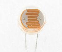
This is a useful dark or light detector switch based on a ldr
variable resistor
and an op-amp TL081 as a comparator!
When the light or dark drops down on the ldr sensor the resistance of it changes and makes the voltage on the inverting input of the opamp change too.
When the voltage on the inverting input goes higher than the non inverting,
the output of the opamp goes high.
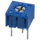
You can set the voltage on the non inverting input via a trimmer to select the brightness threshold you desire.
The opamp drives a relay through a npn transistor and you can then select the output you want (N.O. or N.C.).
You can set the brightness or darkness threshold through a trimmer and you can choose the dark or light operation by swapping the ldr with a resistor!
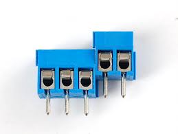
You can select the dark or light functionality at any time via the relay output too, because you have the opportunity to select both the N.O. and N.C. outputs of the relay via a 3pin terminal block.
and an op-amp TL081 as a comparator!
When the light or dark drops down on the ldr sensor the resistance of it changes and makes the voltage on the inverting input of the opamp change too.
When the voltage on the inverting input goes higher than the non inverting,
the output of the opamp goes high.
You can set the voltage on the non inverting input via a trimmer to select the brightness threshold you desire.
The opamp drives a relay through a npn transistor and you can then select the output you want (N.O. or N.C.).
You can set the brightness or darkness threshold through a trimmer and you can choose the dark or light operation by swapping the ldr with a resistor!
You can select the dark or light functionality at any time via the relay output too, because you have the opportunity to select both the N.O. and N.C. outputs of the relay via a 3pin terminal block.
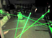
Dark detector as a laser alarm
How to
You can use the dark detector kit as a laser alarm also.
Just point with a laser direct on the ldr and use the n.c contact in series with a zone in your alarm panel. You can add in series many radars or magnetic switches. |
|

After your feedback from the first version we made some improvements
please leave your feedback for the kit or your suggestions for more improvements in the future
|

|
V2 release improvements
1) Reverse polarity protection
2) Redusing the noise in the nets with better pcb wirrings and adding capacitors above the chips.
3) Bigger pads for easier constructions
4) Better placing of the components for easier constructions
5) The on off switch now is extended from the pcb so you can mount it in your project box
6) More leds per channel for more intensity and better placing for better optical results.
7) Ability to place the led on the bottom side so you can hide the rest of the structure.
8) The trimmers are now extended from the pcb board so you can mount them in your project box.
9) Bigger heat sink power plates for better heat consumption.
10) A bigger amplification of the bass indicators.
the circuit schematic
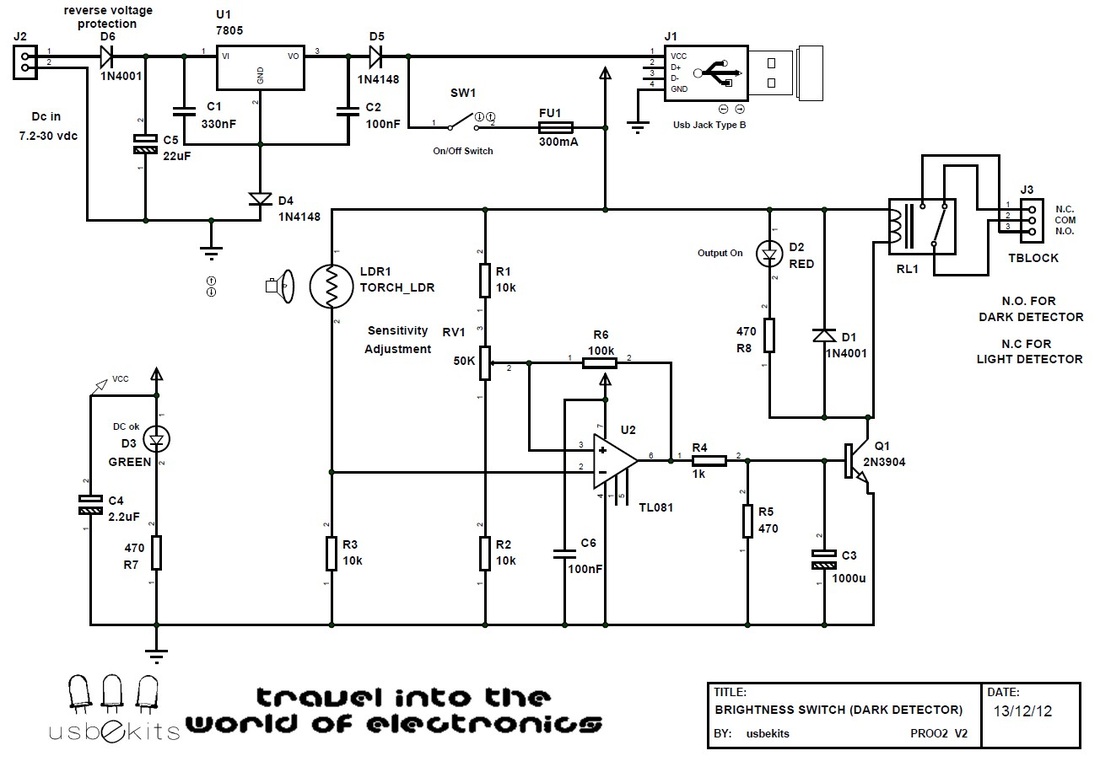
Dark detector schematic
part list
Ref. Type Value
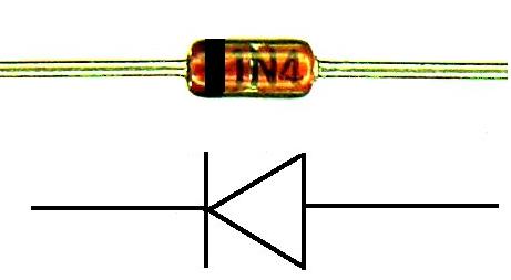
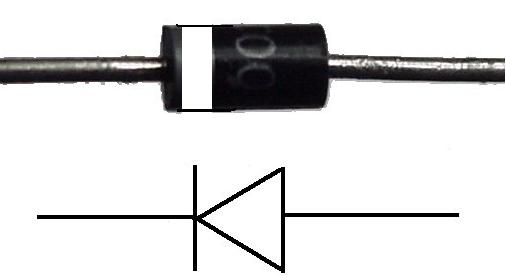
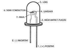
C1 Ceramic Capacitor 330nF C2 Ceramic Capacitor 100nF C3 Electrolytic Capacitor 1000u C4 Electrolytic Capacitor 2.2u C5 Electrolytic Capacitor 22u C6 Smd 0603 Capacitor 100nF D1 Rectifier diode 1N4001 D2 3mm Diffused Led Red D3 3mm Diffused Led Green D4 Diode 1N4148 D5 Diode 1N4148 D6 Rectifier diode 1N4001 FU1 Fuse Glass 20mm 300ma J1 Usb jack Type B J2 Terminal Block 2 pin Dc input J3 Terminal Block 3 pin Output contacts SW1 jst 2pin cable ON/OFF Switch U1 Voltage Regulator 7805 Q1 NPN Transistor 2n3904 R1-R3 Resistor 1/4 watt 10k R4 Resistor 1/4 watt 1k R5 Resistor 1/4 watt 470 R6 Resistor 1/4 watt 100k R7 Resistor 1/4 watt 470 R8 Resistor 1/4 watt 470 U2 Operational Amplifier TL081 LDR1 Light Dep. Resistors Variable RL1 Relay double contacts 5V coil RV1 jst 3pin cable Trimmer 50k |
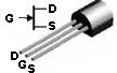
construction help guide
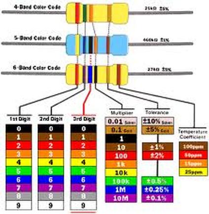
resistor color code definition
|


downloads
| dark_detector_v2_datasheet.pdf |
| dark_detector_v2__merged.pdf |
Set the dark or light threshold to operate the switch via the trimmer
|
|
|