
usb e kits presents
Dc to dc converter
|
|
|
specifications
This is high performance DC-DC Step Down Ajustable Power Supply Module. Based on well know LM2756 Switching Regulator.
-Input voltage range: 4 V-40 V
-Output voltage range: 1.25 V-35 V via trimmer (see picture)
-Output current: 3 A(MAX)-need to add heat sink
-Conversion efficiency: Up to 92% (output voltage higher, the higher the efficiency)
-Switching Frequency: 150KHz
-Rectifier: Non-Synchronous Rectification
-Module Properties: Non-isolated step-down module (buck)
-Short circuit protection: current limiting, since the recovery
-Load regulation: ± 0.5% -Voltage regulation: ± 0.5%-Dynamic response speed: 5% 200uS-Mode of connection:welding-Size:25mm*50mm (2 inch * 1 inch)
The LM2576 series of regulators are monolithic integrated circuits ideally
suited for easy and convenient design of a step–down switching regulator
(buck converter). All circuits of this series are capable of driving a 3.0 A load
with excellent line and load regulation. These devices are available in fixed
output voltages of 3.3 V, 5.0 V, 12 V, 15 V, and an adjustable output version.
These regulators were designed to minimize the number of external
components to simplify the power supply design. Standard series of
inductors optimized for use with the LM2576 are offered by several different
inductor manufacturers.
Application s
-DIY mobile power supply
-Step-down charger
-Electronic equipment charger
-System preceding stage charger
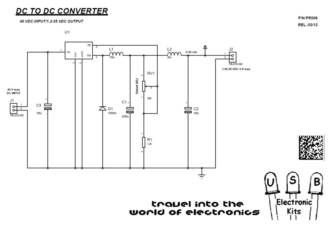
Dc to Dc converter schematic
part list
Reference Type Value
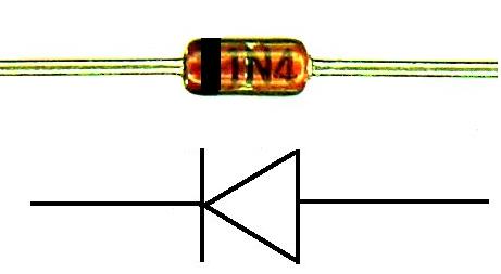
C1 Ceramic Capacitor 2200uF C2 Ceramic Capacitor 100uF C3 Electrolytic Capacitor 100uF U1 Voltage regulator LM2576 L1 Inductor 150uH L2 Inductor 20uH D1 Diode 1N5822 J1 Terminal Block 2 pin J2 Terminal Block 2 pin R1 Resistor 1/4 watt 1.2k RV1 trimmer 50k |
construction help guide
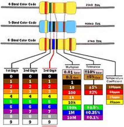
resistor color code definition
|


downloads
| dc_to_dc_converter.datasheet.pdf |