
usb e kits presents
555 pwm controller
|
|
|
functionality
This is a simple pwm controller based on the famous 555 timer chip.
It is necessary for dc devices that needs to be dimmed like high power leds,motors,fans e.t.c.
There isn't enough talk about this circuit.
With the potentiometer you can adjust the pulse length of the output.
With the capacitor c2 you can change the frequency of the output.
By default and with the C2 at 10nf the output is rated at few khz.
The bigger the capacitor the smaller the frequency.
The circuit can operates in a wide input voltage range beginning from 5 volts and up to 18 volts.
The output can sink current up to 4 amps.
If necessary attach a heat sink on the mosfet.
the power transition to the output is 5-95%.
Technical Features
Layers :2
PCB Thickness : 1.6mm
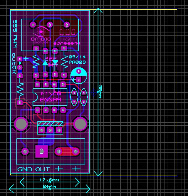
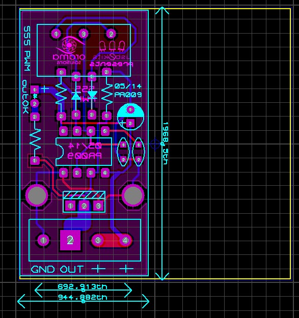
Dimensions : 50 mm x 24 mm ( 2 inch x 1 inch )
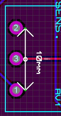
Mounting holes dist:17.8mm
Operating Voltage : 5-18 Vdc .
Operating current : 20 ma
Output sink current: 4 amps max
Rel.date:17/05/14
It is necessary for dc devices that needs to be dimmed like high power leds,motors,fans e.t.c.
There isn't enough talk about this circuit.
With the potentiometer you can adjust the pulse length of the output.
With the capacitor c2 you can change the frequency of the output.
By default and with the C2 at 10nf the output is rated at few khz.
The bigger the capacitor the smaller the frequency.
The circuit can operates in a wide input voltage range beginning from 5 volts and up to 18 volts.
The output can sink current up to 4 amps.
If necessary attach a heat sink on the mosfet.
the power transition to the output is 5-95%.
Technical Features
Layers :2
PCB Thickness : 1.6mm
Dimensions : 50 mm x 24 mm ( 2 inch x 1 inch )
Mounting holes dist:17.8mm
Operating Voltage : 5-18 Vdc .
Operating current : 20 ma
Output sink current: 4 amps max
Rel.date:17/05/14
the circuit schematic
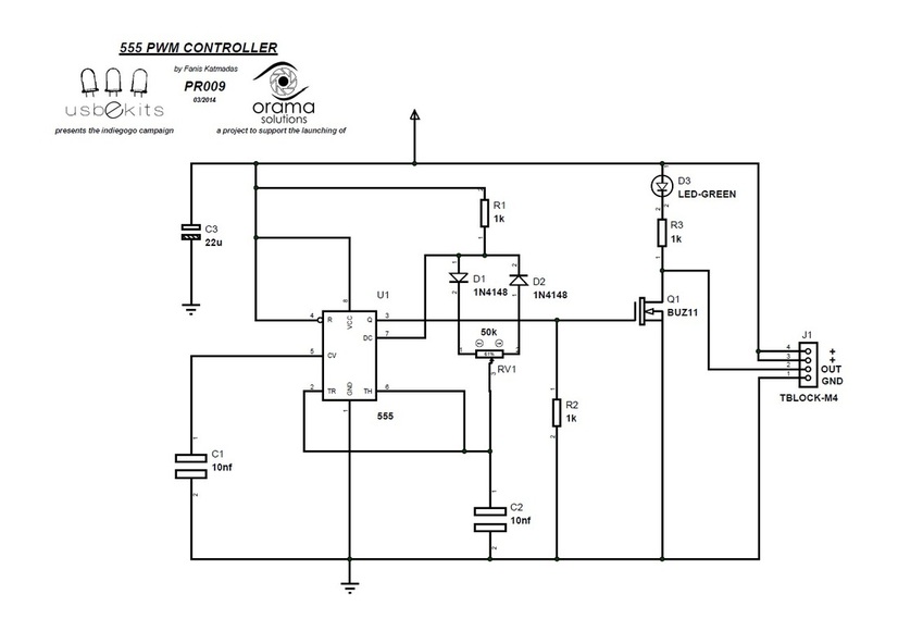
555 pwm controller
Dimensions
|
|
part list
Ref. Type Value
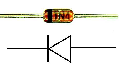
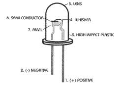
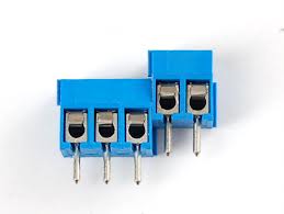
C1 Ceramic Capacitor 10nF C2 Ceramic Capacitor 10nF C3 electrolytic capacitor 22uf D1 high speed diode 1n4148 D2 high speed diode 1n4148 D3 3mm difused led Green J1 Terminal Block 6 pin Dc input & sink outputs Q1 n-channel mosfets irfz44n R1 Resistor 1/4 watt 1k R2 Resistor 1/4 watt 1k R3 Resistor 1/4 watt 1k U1 timer chip 555 RV1 potentiometer 50k |
construction help guide
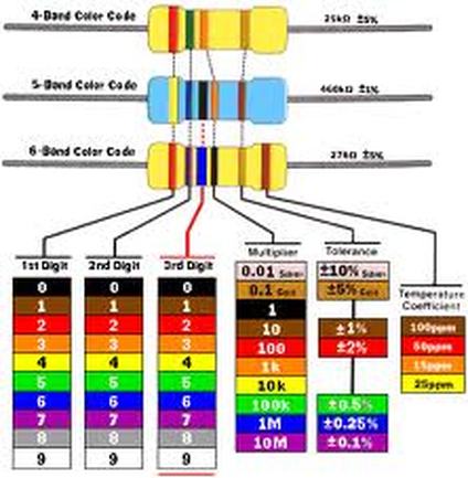
resistor color code definition
|

downloads
| 555_pwm__datasheet.pdf |
| pcb_555_pwm_controller.pdf |