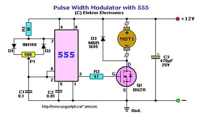
The regulation is obtained via PWM or Pulse Width Modulation. The output pin 3 of the 555 provides square-wave with an adjustable duty-cycle. What that basically means is that the pulse width changes the speed of the motor. The output from the 555 feeds the mosfet via current limiting resistor R2 of 47 ohms. Because the MosFET Q3 only "switches" and is not behaving like a pot, its energy-waste level is negliable, and also provides the motor more coupling at low rpm. The maximum current Q1 can provide (safely) is about 10A.
link to the circuit page<-------

 RSS Feed

