usbekits
  • HOME
  • ELECTRONICS
    • OUR KITS >
      • COLOR ORGAN external lights
      • 555 PWM CONTROLLER
      • CLAP SWITCH
      • DARK DETECTOR
      • RGB MOOD LAMP
      • COLOR ORGAN
      • LED VOLTMETER
      • DC TO DC CONVERTER
    • CALCULATORS & CONVERTERS
    • SOLDERING & PROTOTYPING
    • PICTORIALS
    • CIRCUITS AND TUTORIALS
    • DATASHEETS
  • 3D PRINT
    • CUSTOM LED MACHINE VISION
  • PROJECTS
    • 3 FLOOR ELEVATOR LOGO
    • 3 FLOOR ELEVATOR ARDUINO
    • ARDUINO I/O BOARD
    • VERTICAL AXIS WIND TURBINE
    • MOBILE SOLAR PANEL
  • BLOG / NEWS
  • CONTACT US
  • ORAMA
  • LINKS

A more friendly to use schematic for Clap switch kit

3/14/2014

0 Comments

 
Picture
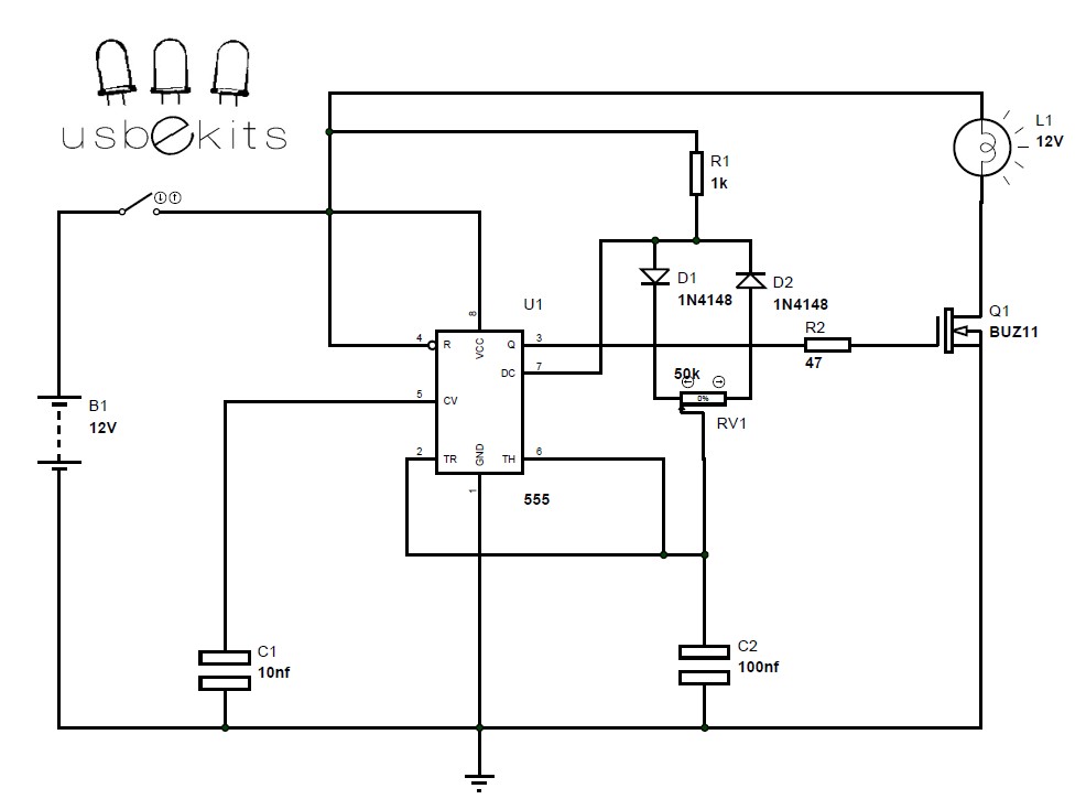
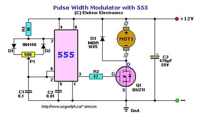
As I notice a lot of people get confused when they try to build their own schematic. The complexicity in the power input is one of the major problems for the usb power input.So i decide to design a more friendly schematic for those who want to use a 12 power supply only directly.So have a look at this.

0 Comments

MC34063 step up , step down calculator

11/27/2013

2 Comments

 
Picture
Fill in the form and push "Calculate" to get an updated schematic.
link here<----

2 Comments

12 vdc version color organ with mosfets

11/16/2013

1 Comment

 
Picture12 vdc colr organ schematic
Due to a lot of interest in the circuit of the color organ kit i decide to make a more simple circuit operating under 12 volts .
Please feel free to ask for definitions


1 Comment

555 with diode trigger network in monostable mode

9/10/2013

0 Comments

 
Picture555 with diode trigger network in monostable mode

0 Comments

Battery reverse polarity protection circuit by usbekits

9/3/2013

0 Comments

 
Picture
As you've already realized we love make the things simple...
This is a way i prefer to protect some circuits and varius loads from a reversed battery...

We all make mistakes so a protection is n

0 Comments

555 timer pwm controller

9/1/2013

1 Comment

 
Picturepwm 555 timer controller
This is  a simple circuit based on the famous 555 timer...
With this circuit you can control any load you want but consider first the switching component that the 555 will control....
The n-channel mosfet buz11 can handle 30A and up to 50volts...
You can operate the device connected on the switching component from 5% to 95%.

1 Comment

Pulse width modulation using 555

6/27/2013

1 Comment

 
Picture
This circuit is capable of regulating 12V motors and DC light bulbs. No coolrib required for Q1 or D3 if the current does not exceed 2A. If it does, a sufficient coolrib for both the Schottky Diode (D3) and MosFET Q1 is required.
The regulation is obtained via PWM or Pulse Width Modulation. The output pin 3 of the 555 provides square-wave with an adjustable duty-cycle. What that basically means is that the pulse width changes the speed of the motor. The output from the 555 feeds the mosfet via current limiting resistor R2 of 47 ohms. Because the MosFET Q3 only "switches" and is not behaving like a pot, its energy-waste level is negliable, and also provides the motor more coupling at low rpm. The maximum current Q1 can provide (safely) is about 10A.

link to the circuit page<-------

1 Comment

Symetrical output with single power supply

6/13/2013

2 Comments

 
Picture
The circuit has been made for the creation of a symmetrical voltage that would come from a single power supply.
The circuit is providing the possibility the possibility of producing a symmetric voltage as required for some applications. This will always come from the existing single power supply of the circuit which is made possible by the use of IC1 L165. The voltage output is symmetrical in nature compared to the normal output.

2 Comments

design of switching power supplies

3/9/2013

1 Comment

 
Picture
The following programs calculate the relevant currents and voltages for various switch mode power supplies and display these graphically. Furthermore the programs give suggestions for appropriate choking coils and high frequency transformers.
                                                                                       explore here<---

1 Comment

0-5 V led monitor - voltage level indicator

1/14/2013

0 Comments

 
Picture
0-5v led volt meter lm3914

0 Comments
<<Previous

    usbekits

    Read our latest Posts!Share your thoughts!Edit your comments here!
    This blog started at 20/10/12

    Archives

    May 2014
    March 2014
    December 2013
    November 2013
    October 2013
    September 2013
    July 2013
    June 2013
    April 2013
    March 2013
    February 2013
    January 2013
    December 2012
    November 2012
    October 2012

    Categories

    All
    Admin
    Circuits
    Datasheets
    Educate
    Electronic Parts
    Links
    Pictorials
    Site Updates

    RSS Feed

    Picture
Powered by Create your own unique website with customizable templates.