usbekits
  • HOME
  • ELECTRONICS
    • OUR KITS >
      • COLOR ORGAN external lights
      • 555 PWM CONTROLLER
      • CLAP SWITCH
      • DARK DETECTOR
      • RGB MOOD LAMP
      • COLOR ORGAN
      • LED VOLTMETER
      • DC TO DC CONVERTER
    • CALCULATORS & CONVERTERS
    • SOLDERING & PROTOTYPING
    • PICTORIALS
    • CIRCUITS AND TUTORIALS
    • DATASHEETS
  • 3D PRINT
    • CUSTOM LED MACHINE VISION
  • PROJECTS
    • 3 FLOOR ELEVATOR LOGO
    • 3 FLOOR ELEVATOR ARDUINO
    • ARDUINO I/O BOARD
    • VERTICAL AXIS WIND TURBINE
    • MOBILE SOLAR PANEL
  • BLOG / NEWS
  • CONTACT US
  • ORAMA
  • LINKS

color organ v2.2 update

3/3/2013

0 Comments

 
Picture
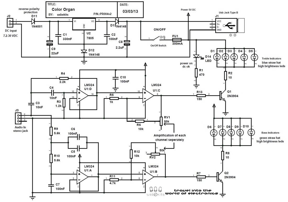
Color organ v2.2 schematic
I've changed the values of the resistors R11 , R12 , R6.
This is for the amplification level of the signal.
I think that the previous values offered bigger amplification than we wanted.
So now we have more flexibility with the audio levels of the signal.
New values: R6 =10K , R11=4,7K , R12=10K

0 Comments


Leave a Reply.

    usbekits

    Read our latest Posts!Share your thoughts!Edit your comments here!
    This blog started at 20/10/12

    Archives

    May 2014
    March 2014
    December 2013
    November 2013
    October 2013
    September 2013
    July 2013
    June 2013
    April 2013
    March 2013
    February 2013
    January 2013
    December 2012
    November 2012
    October 2012

    Categories

    All
    Admin
    Circuits
    Datasheets
    Educate
    Electronic Parts
    Links
    Pictorials
    Site Updates

    RSS Feed

    Picture
Powered by Create your own unique website with customizable templates.